
Portfolio
Engine Torque Mount Redesign – Volvo P3 Chassis & Range Rover Platforms
Project Overview: Final capstone project focused on redesigning an engine torque link for high-load, high-vibration automotive environments. The design was tailored to fit the P3 Volvo chassis and various Range Rover configurations.
Design Objectives:
Increase torsional stiffness and vibrational rigidity to reduce drivetrain deflection and improve vehicle handling response.
Compare performance across two material configurations using advanced FEA techniques.
Improve bushing performance by replacing OEM natural rubber (approx. 60A durometer) with 80A polyurethane for better longevity and load response.
Modeling & Simulation:
Created 3D CAD geometry in SolidWorks and exported to ANSYS Workbench for simulation.
Conducted three types of finite element analyses:
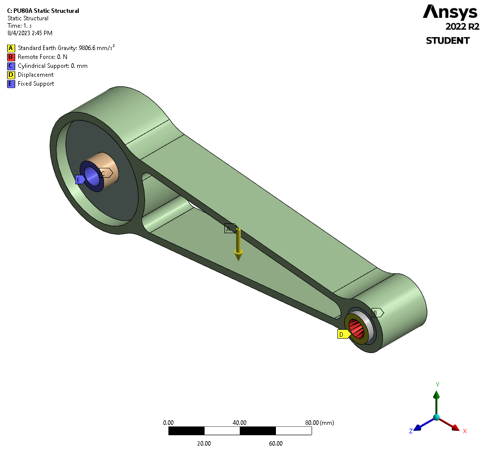
Static Structural Analysis: Applied a 500 N·m torque and constrained mounting points to evaluate linear elastic behavior, identifying high-stress zones around bushing interfaces and weld seams.
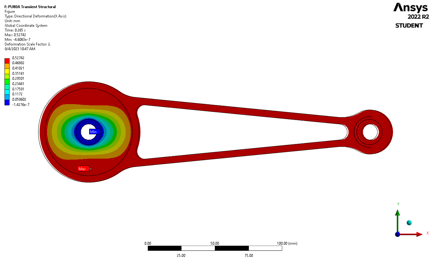
Transient Structural Analysis: Simulated engine torque pulses over time (~30 Hz) to assess dynamic load effects and bushing deformation under cyclic loading.
Modal Analysis: Evaluated natural frequencies and mode shapes; redesigned geometry to shift the first critical mode above 110 Hz to avoid engine harmonic resonance.
Key Performance Metrics:
Torsional stiffness increased by 35%, improving drivetrain control under sudden acceleration or deceleration.
Peak deflection reduced by 28%, minimizing engine rocking and bushing wear.
First natural frequency raised by 25%, from ~95 Hz to ~119 Hz, enhancing NVH isolation performance.
Achieved a 15% overall weight reduction by selecting high-strength low-alloy steel over aluminum in critical areas while maintaining factor-of-safety > 2.0.
Bushing Redesign:
Implemented cylindrical 80A polyurethane inserts with bonded aluminum sleeves.
Improved fatigue life and heat resistance over OEM bushings, suitable for aggressive driving cycles and elevated under-hood temperatures (~120–140 °C).
Outcome:
Delivered a fully validated CAD and FEA model with documented stress contours, modal plots, and transient displacement graphs.
Presented results in a formal design review and received top marks for technical depth and analysis accuracy.


NASA Lunabotics Challenge 2023 – University of North Dakota
Role: Lead Mechanical Engineer | Team earned 2nd Runner-Up overall among 40+ university teams
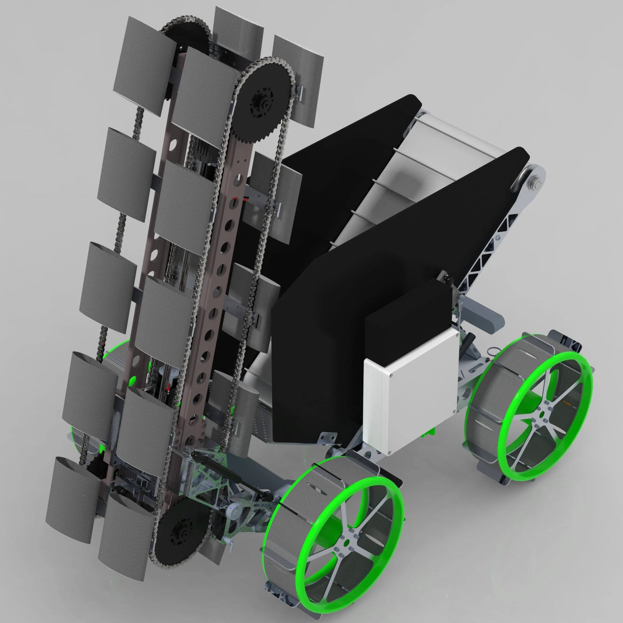
Project Overview: Designed, built, and tested a lunar excavation robot (Lunabot) for NASA's annual competition simulating in-situ resource utilization (ISRU) on the Moon. Tasks included autonomous regolith excavation, traversal of uneven terrain, and simulant delivery within strict mass, volume, and energy constraints.
Leadership & Responsibilities:
Led the mechanical subsystem team of 6 members, overseeing CAD, structural design, drivetrain development, and excavation hardware integration.
Facilitated cross-functional coordination with electrical and software teams to ensure mechanical interfaces and tolerances met system integration needs.
Developed and enforced the team’s design verification plan, including FEA, tolerance stack-ups, and component-level testing for mobility and durability.
Managed procurement and fabrication schedule to maintain alignment with NASA’s design review deadlines (SRR, CDR, and TRR).
Design & Technical Contributions:
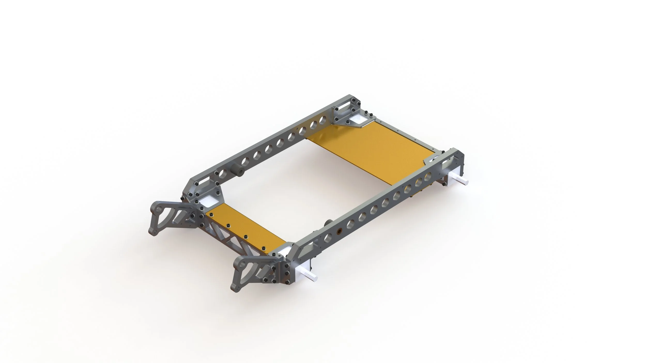
Architected the chassis and frame to meet NASA’s volume constraints (≤ 1.5 m x 0.75 m x 0.75 m) while maintaining structural rigidity under excavation loads.
Designed a modular excavation system featuring a dual-stage bucket ladder, allowing rapid prototyping and replacement of high-wear components.
Implemented a 4-wheel drive system for enhanced terrain compliance and improved obstacle traversal over BP‑1 simulant.
Selected materials (aluminum 6061-T6, HDPE wear plates) to optimize the strength-to-weight ratio, contributing to a total mass under 75 kg.
Performance Highlights:
Achieved an estimated 9–12 kg regolith simulant collection per run, meeting NASA’s minimum excavation benchmarks.
Integrated semi-autonomous waypoint navigation with positional error within ±15 cm and maintained full mission completion within the 15-minute cycle.
Contributed to UND’s 3rd-place award in NASA’s “Proof-of-Life” media category, showcasing mission capability and mechanical performance.
Outreach & Results:
Participated in STEM outreach events, engaging local K–12 students with lunar robotics demos and FIRST Robotics mentorship.
Supported design documentation and presentation for NASA’s design reviews and UND College of Engineering public showcases.
Created in PTC Creo 9.0


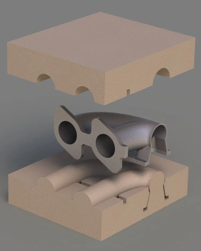
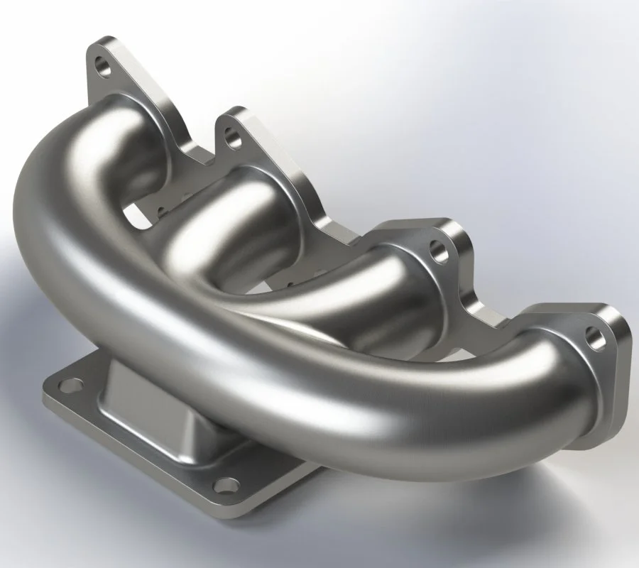
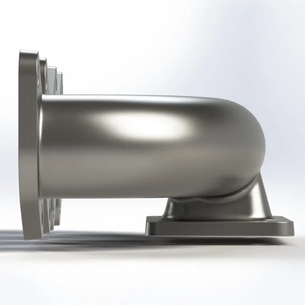
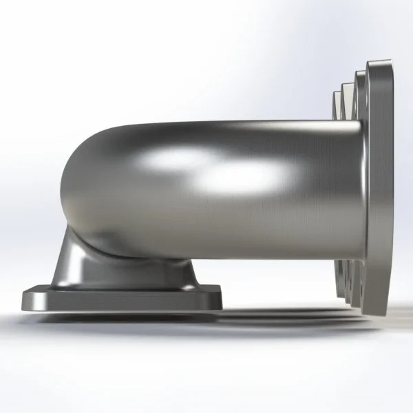
4-Cylinder Turbo Exhaust Manifold Design – Green Sand Casting Project
Course: Manufacturing Processes – Final Project
Objective: Design a multi-process component combining green sand casting and precision machining.
Component Overview:
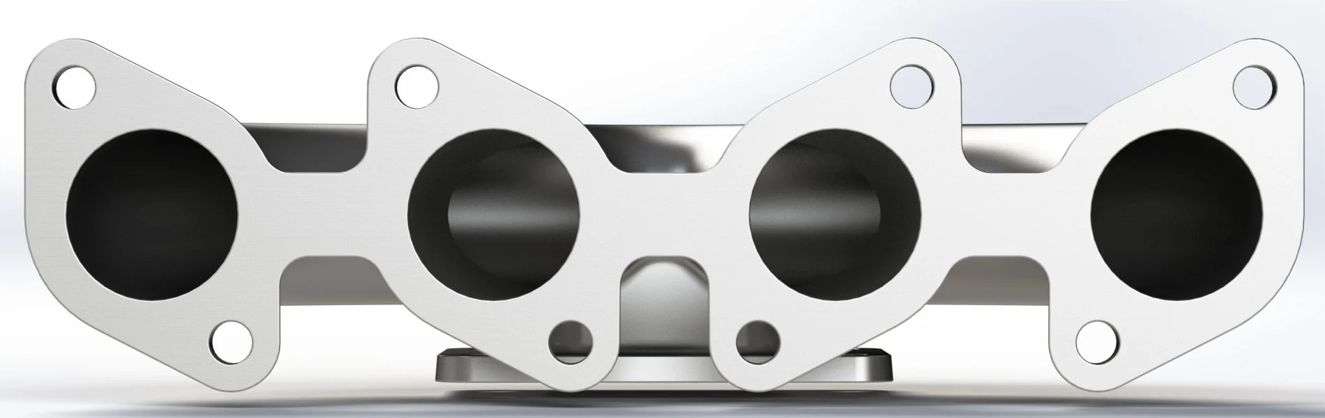
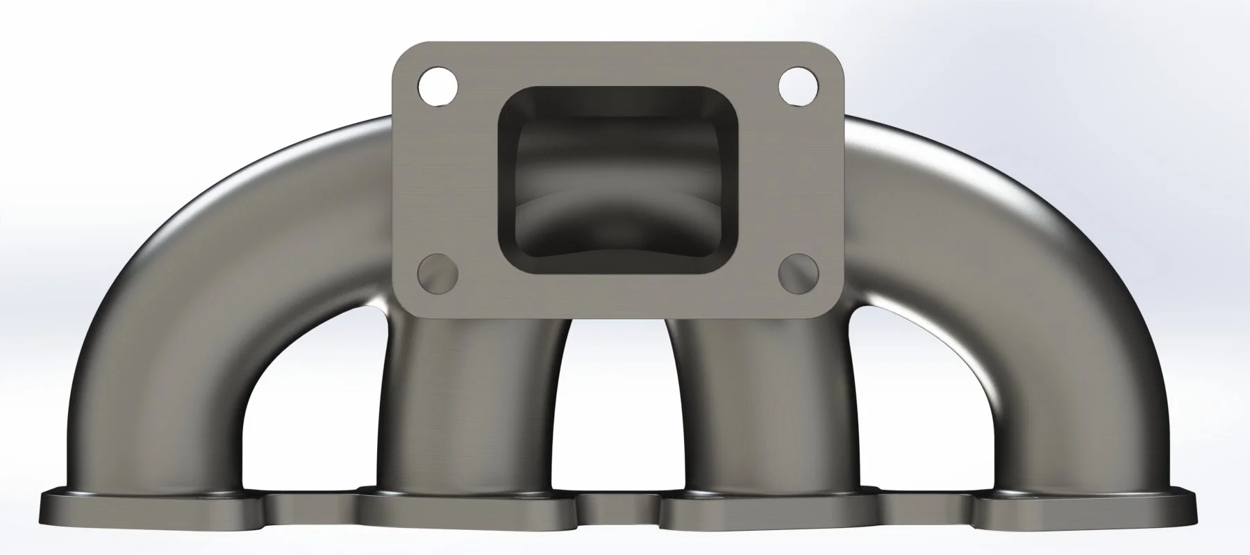
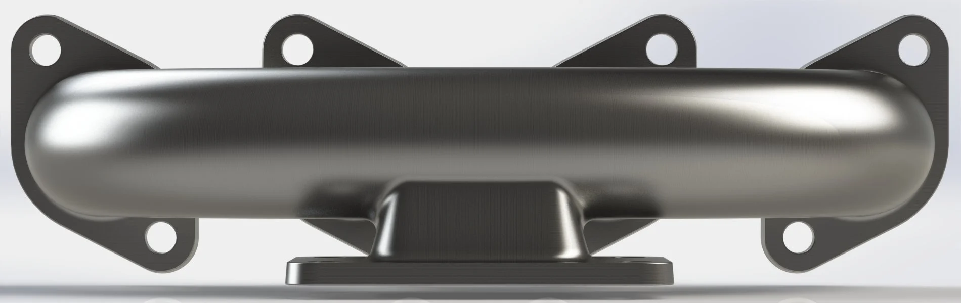
Developed a 4-into-1 turbo exhaust manifold with a standard T3 turbine flange for a generic 4-cylinder engine.
Target material: Cast stainless steel (CF8M or 304 equivalent) for high-temperature resistance (>800 °C) and corrosion durability.
Runners designed for near-equal lengths (~280–320 mm) with gradual merge angles (<15°) to minimize turbulence and maintain exhaust velocity.
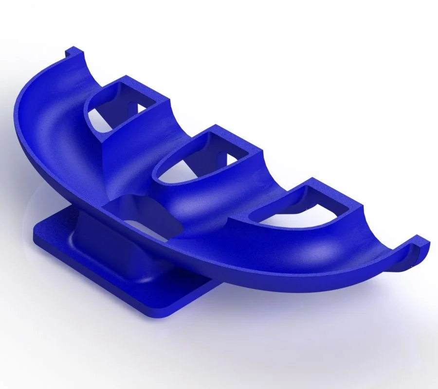
Casting Design & Process Planning:
Created a complete cope-and-drag mold assembly with removable sand cores for hollow runners.
Incorporated key green sand casting allowances:
Draft angle: 2–3° on vertical surfaces to enable pattern removal
Shrinkage allowance: ~2% linear (common for stainless steel)
Machining allowance: ~1.5–2.0 mm on flanges and port faces
Minimum wall thickness: 4.5–6.0 mm for structural durability and flow control
Designed a gating and riser system sized for ~5 kg total casting mass with a fill time of <15 seconds (targeting Chvorinov’s Rule compliance).
Machining Operations:
Post-casting features included:
CNC-machined T3 flange with bolt circle tolerance of ±0.05 mm
Milled runner ports to match gasket profile within ±0.2 mm
Surface finishing of mating faces to Ra ≤ 3.2 µm for gasket sealing
Drilled and tapped M10 × 1.5 bolt holes with 20 mm thread engagement
Estimated material removal rate: ~35–50 cm³/min using coated carbide tools at ~200–250 SFM (based on austenitic stainless properties).
Simulation & Manufacturing Considerations:
Applied Chvorinov’s Rule to validate solidification time and prevent cold shuts or shrinkage cavities.
Calculated gating area to maintain flow velocity <0.5 m/s at in-gate to avoid erosion of sand mold.
Considered parting line, venting, and core support strategies to reduce defects such as flash, core shift, or gas porosity.
Outcome:
Delivered a complete digital manufacturing package including:
Parametric 3D model and 2D machining drawings
Mold cavity design with gating, risers, and core prints
Manufacturing plan for pattern making, molding, casting, and CNC post-processing
Project met all process integration objectives and was recognized for manufacturability and real-world application relevance.
Created in PTC Creo 8.0


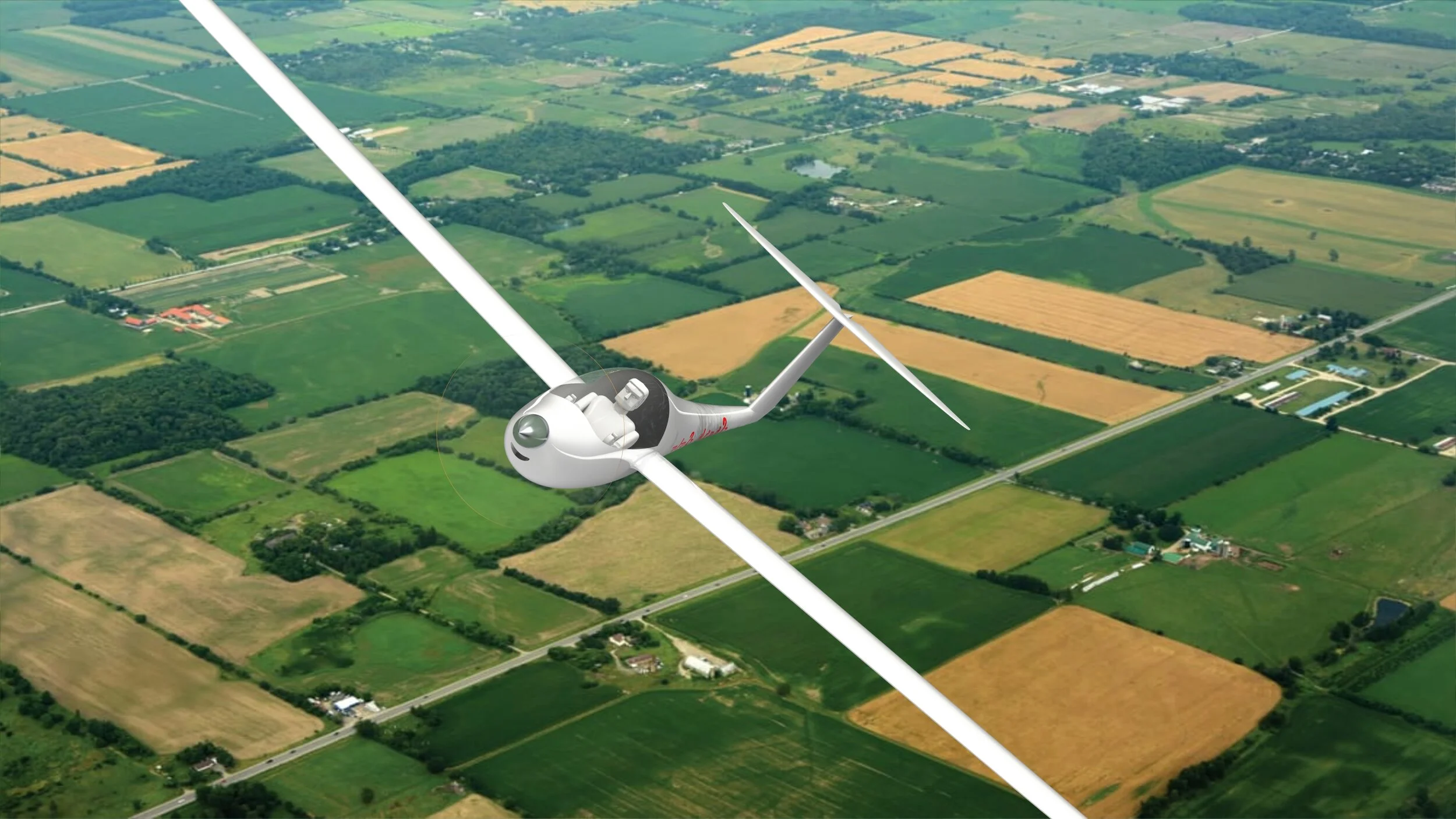
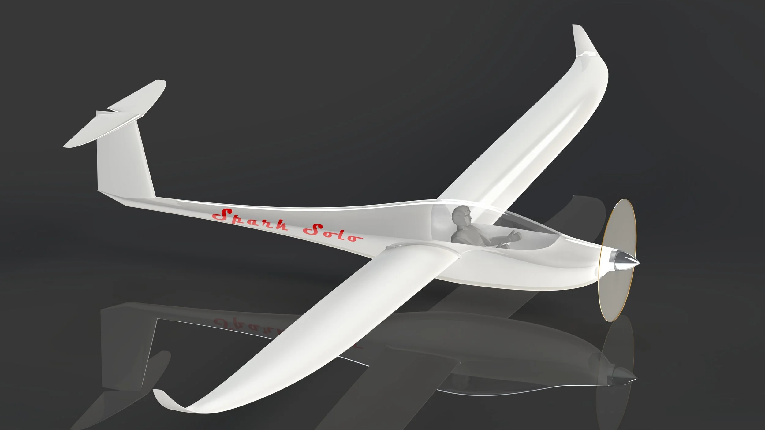
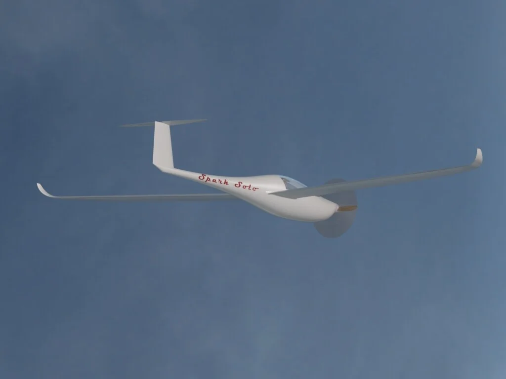
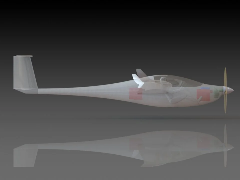
Spark Solo Project
Electric Motor-Glider Design – Volunteer Co-operative Project
Organization: Experimental Aircraft Association (EAA) Chapter 206 & Bremerton Aviation Center for Education
Initiative: Young Eagles STEM Outreach Program
Role: Propulsion Integration Engineer – Volunteer Position
Project Overview:
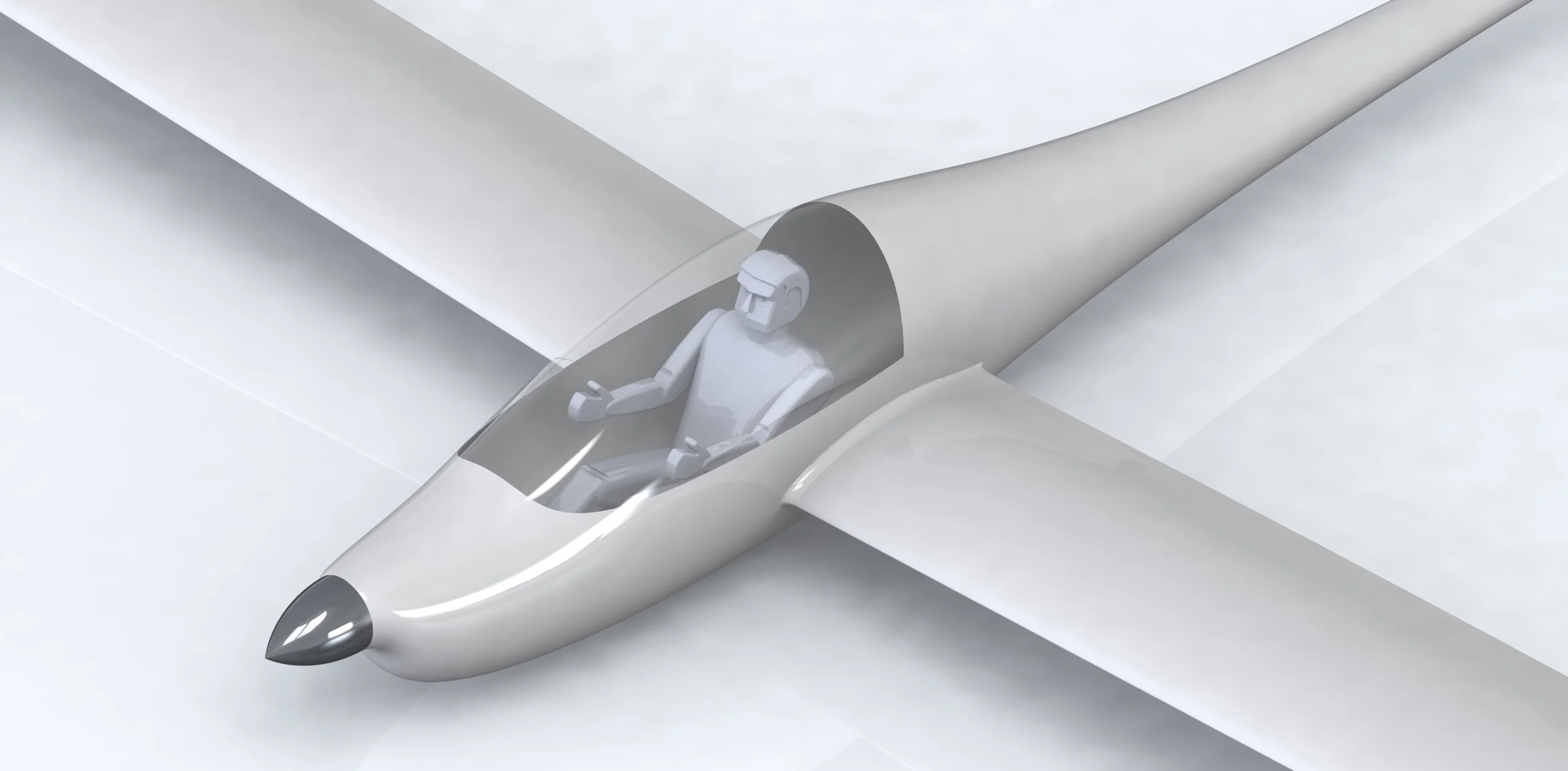
Contributed to a clean-sheet design of a self-launching, electrically powered motor-glider under the guidance of EAA Chapter 206 and BACE.
Project intended to inspire and educate future aerospace engineers and pilots through hands-on design and fabrication, incorporating STEM outreach via the Young Eagles program.
Glider design prioritized low-drag efficiency, lightweight construction, and compliance with experimental aircraft regulations (FAR Part 103 / Light Sport Aircraft design principles).
Responsibilities:
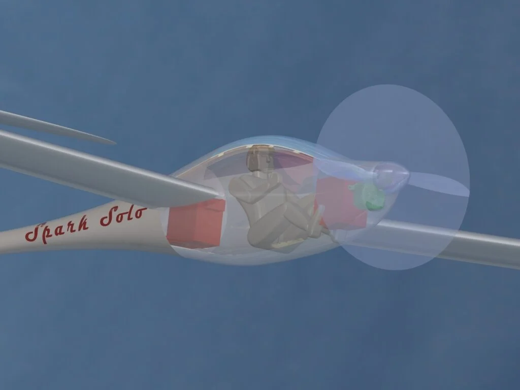
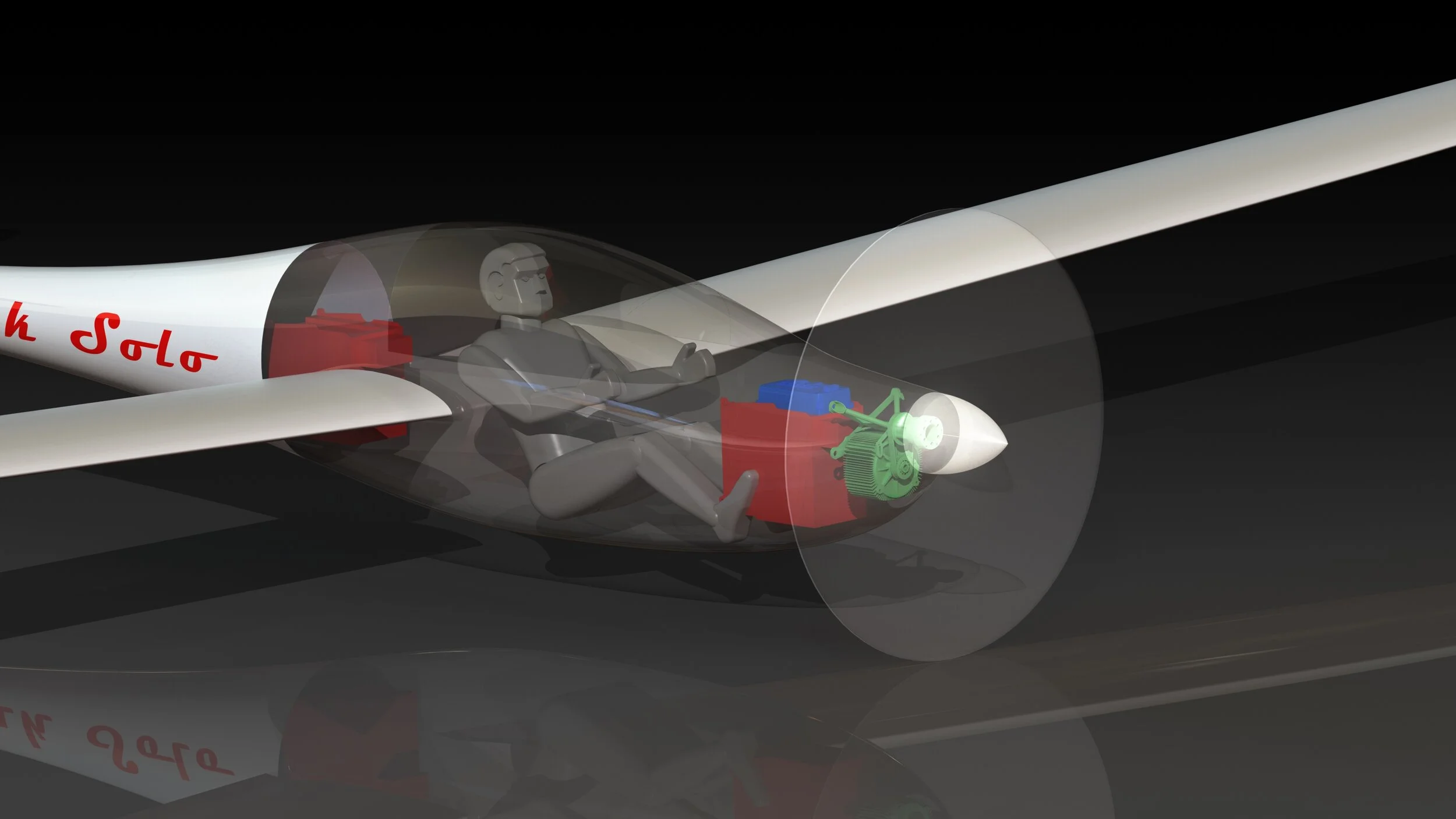
Focused on integration of electric propulsion subsystems into the composite fuselage structure:
Electric motor selection based on power-to-weight ratio, cooling requirements, and torque-speed profile
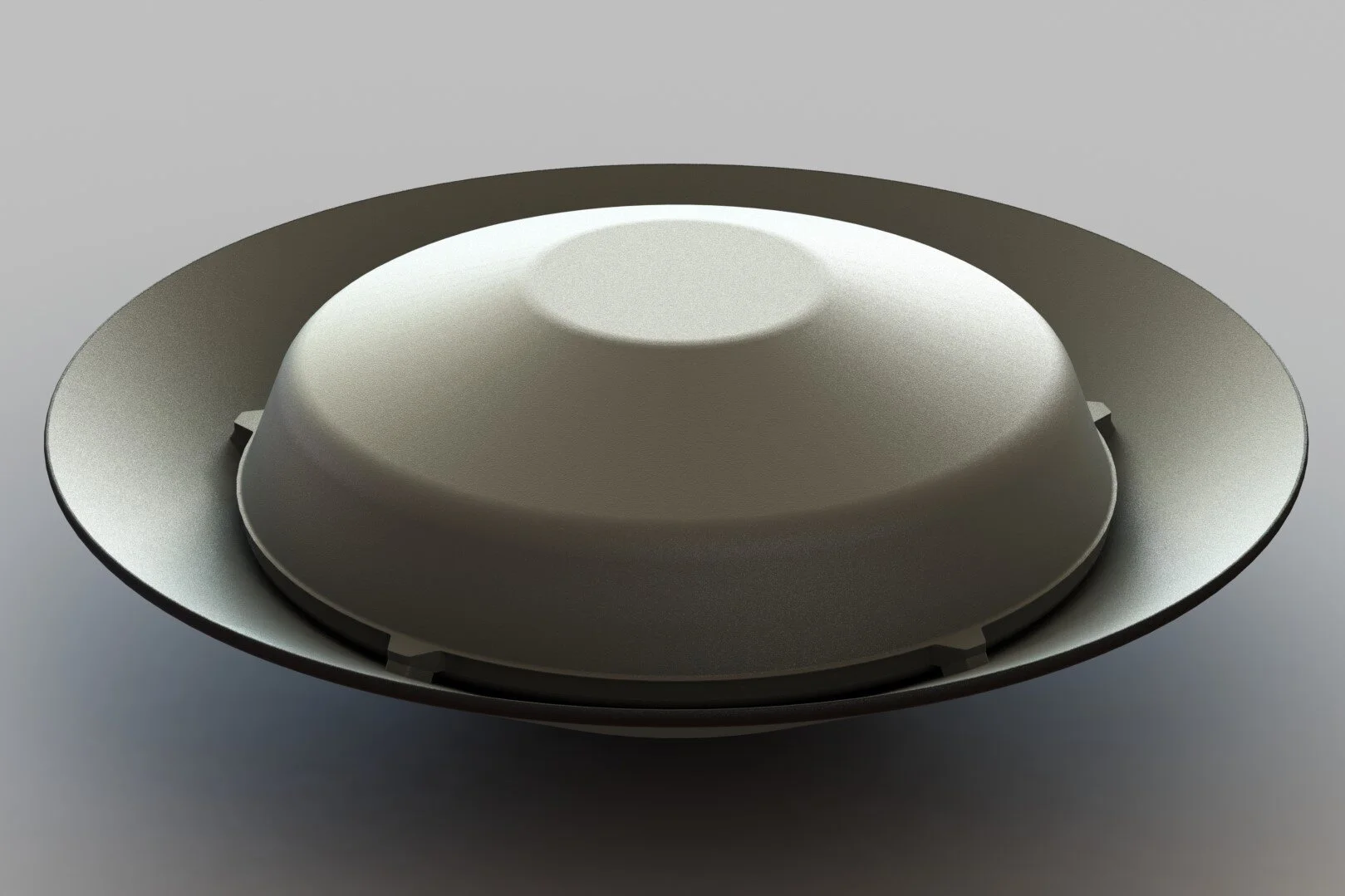
Propeller matching and positioning for optimal thrust and aerodynamic efficiency
Battery system placement, mass distribution, thermal isolation, and access for maintenance/safety
Wiring harness design with routing through composite bulkheads and reinforced conduits
Evaluated mounting strategies for vibration isolation, safety cutoff mechanisms, and serviceability.
Collaborated with cross-functional team including structural designers, avionics engineers, and fabrication mentors.
Design & Integration Considerations:
Target specifications:
Empty weight: <280 kg (within ultralight/motor-glider envelope)
Flight endurance: ≥30 minutes under electric propulsion
Climb rate: ≥1.5 m/s at 75% throttle
Cruise efficiency: <100 W/kg at level flight
Assessed thermal management strategies for battery and ESC systems including passive cooling channels and airflow ducting in fuselage design.
Evaluated center-of-gravity impact of propulsion subsystem and verified compatibility with anticipated flight envelope.
Proposed composite layup modifications (carbon fiber reinforcement) around propulsion mounting points to handle torque and load paths.
Outcomes:
Completed conceptual integration CAD models of propulsion system within fuselage envelope using SolidWorks and integrated FEA software.
Supported technical documentation and system-level schematics for design reviews and FAA experimental aircraft registration planning.
Engaged with board of directors to explain propulsion system fundamentals and design tradeoffs during EAA-hosted design reviews.
Created in SolidWorks 2020


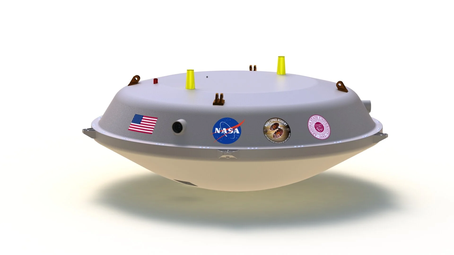
NASA L'SPACE Mission Concept Academy – Titan Lander “Laplace”
Role: Project Manager, Lead Mechanical Engineer, and CAD Designer
Program: NASA L'SPACE Mission Concept Academy (Fall 2019, Team 37)
Mission Concept: Laplace Trieste Titan Mare Explorer (LBTP)
Mission Scope:
Designed a conceptual lander to explore Kraken Mare, the largest hydrocarbon sea on Saturn’s moon Titan.
Objective: investigate abiogenesis by collecting atmospheric and liquid data in conditions analogous to primordial Earth.
Delivered a complete Preliminary Design Review (PDR) within a 12-week accelerated NASA-style program under JPL mentorship.
Leadership Responsibilities:
Managed a multidisciplinary team of 10+ students across mechanical, electrical, and systems engineering roles.
Directed technical timeline, design reviews, subsystem integration, and deliverables across all phases of the program.
Facilitated communication with NASA mentors and served as the primary liaison for project updates and team coordination.
Mechanical & CAD Design:
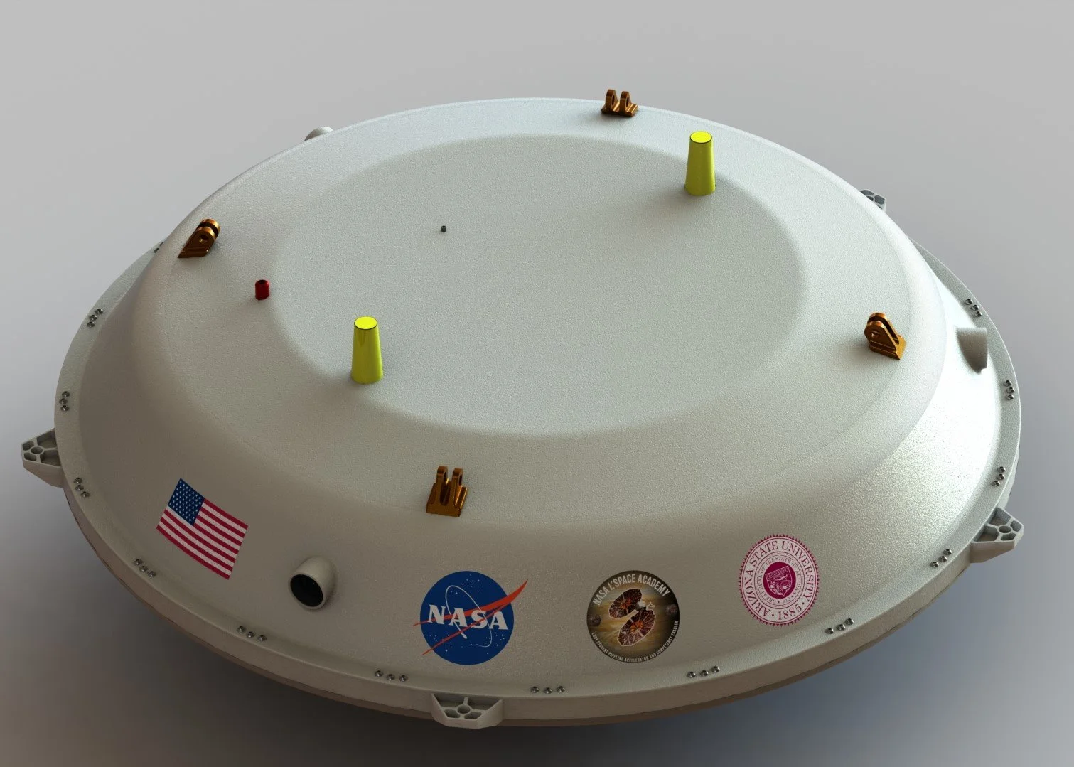
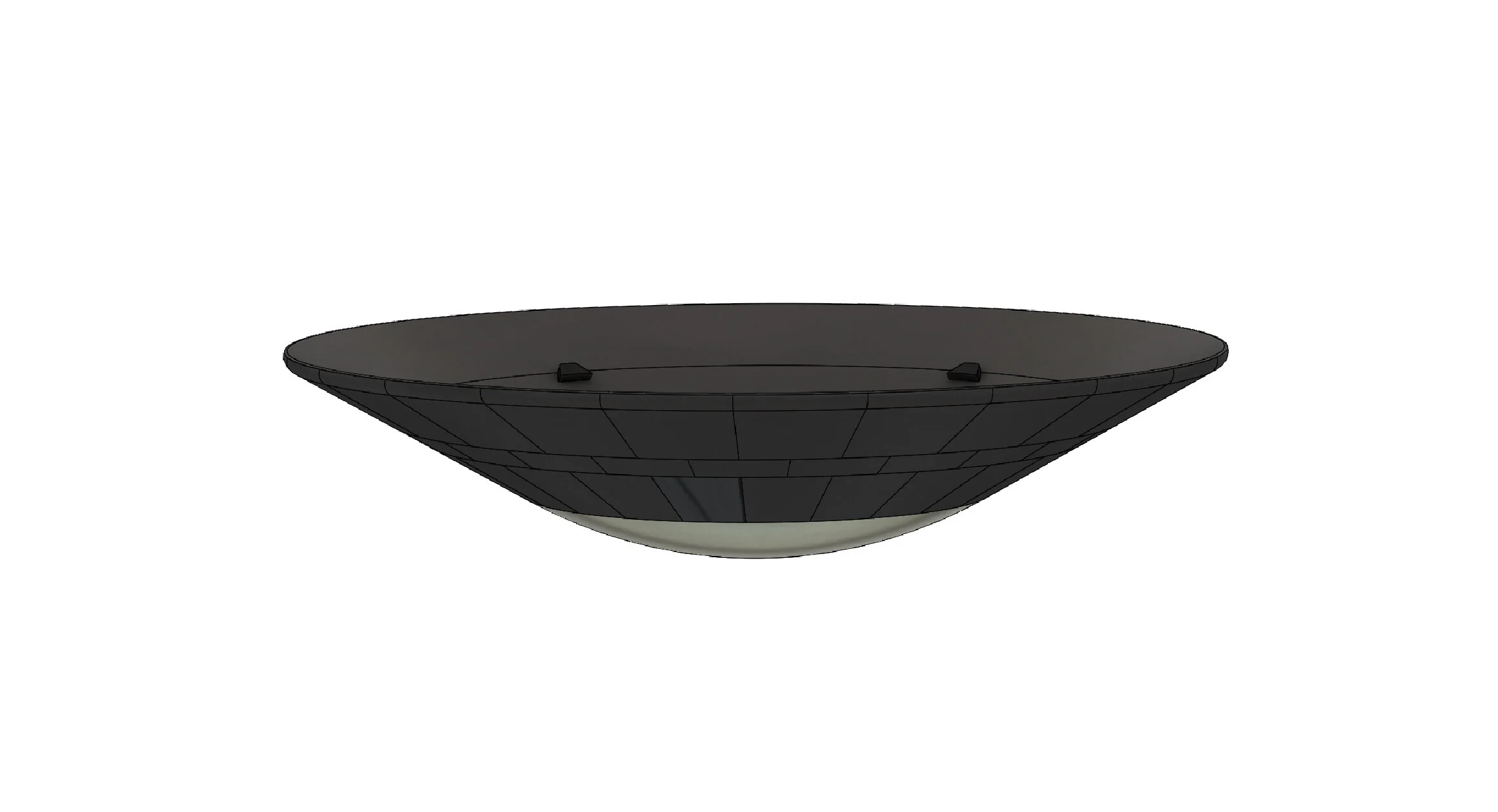
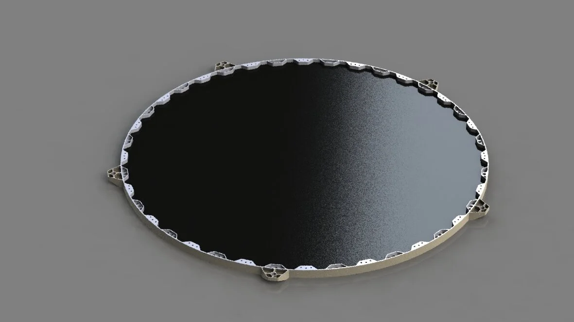
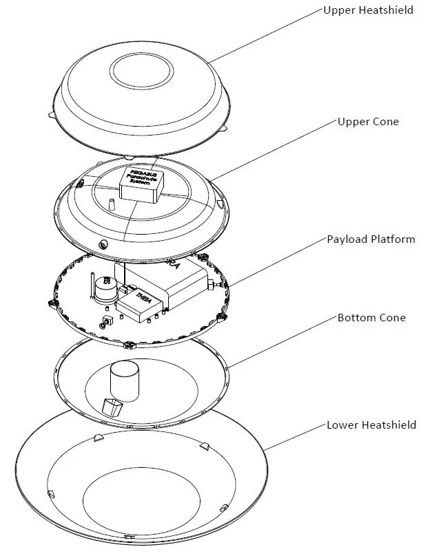
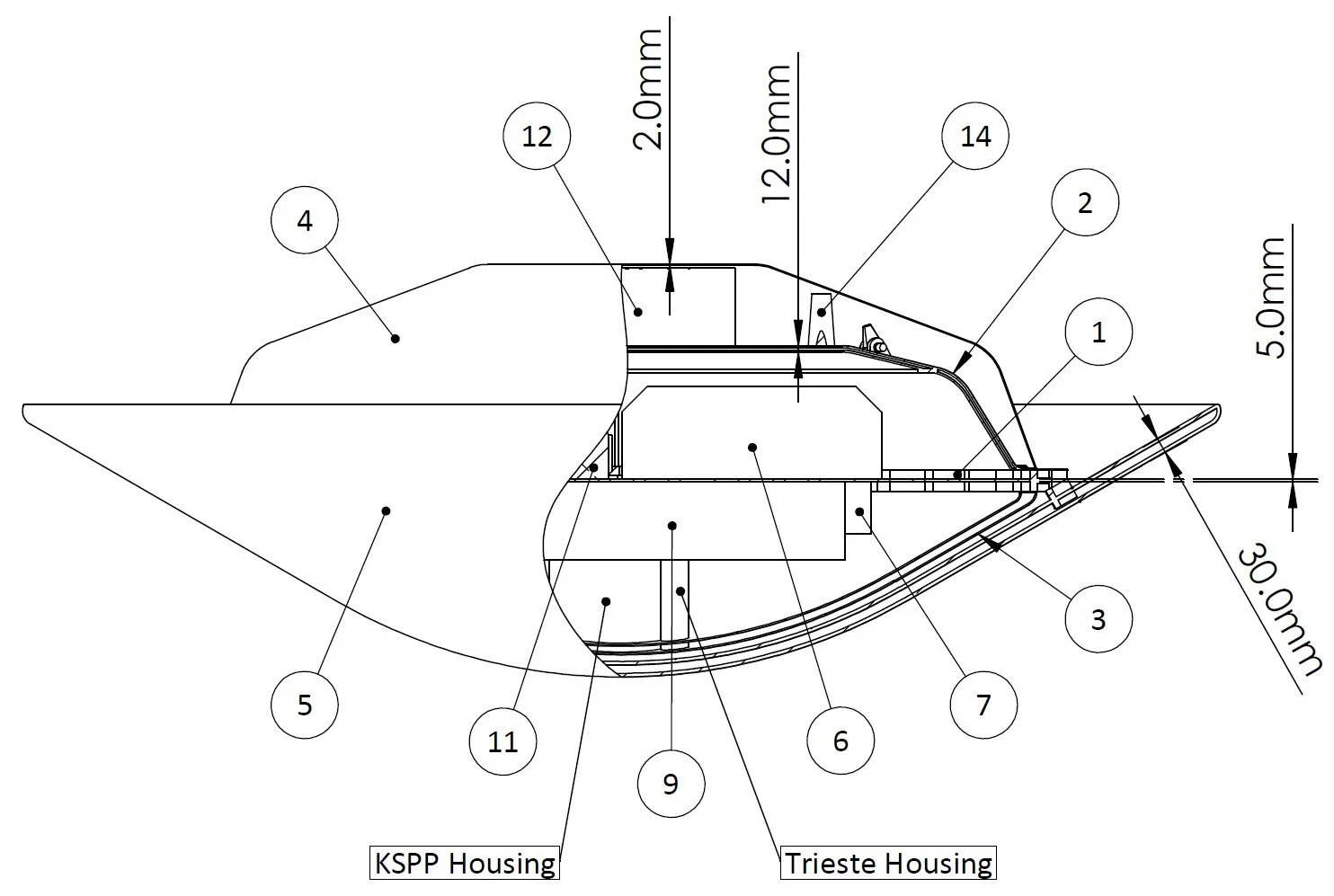
Created detailed 3D CAD models of the Laplace lander, payload platform, and Trieste submersible using SolidWorks.
Engineered a buoyant capsule configuration inspired by Apollo-style capsules, capable of splashdown at <7 m/s on a cryogenic liquid surface.
Designed for operation in 98 K temperatures and 1.5 bar pressure using carbon fiber (AS4C) and aerospace-grade aluminum (6061/5051).
Performed volume, mass, and buoyancy calculations to ensure stable flotation and structural survivability under Titan conditions.
Scientific Payload & Subsystems:
Integrated four scientific payloads and four camera systems, including:
IRIS – Gas Chromatograph Mass Spectrometer for hydrocarbon analysis
LASI & LAPI – Acoustic sonar & speed-of-sound measurement
LASP – Submersed cryogenic temperature probe
THEIA – Imaging suite with CMOS, IR, and video cameras
Designed housing for Trieste, a deployable bathythermograph probe to measure vertical profiles of temperature and pressure in Kraken Mare.
Ensured subsystem compatibility with RS422 protocols, space-qualified batteries, and a radiation-hardened RAD750 processor.
Key Performance Metrics:
Lander mass: 176.1 kg; volume: 0.856 m³; buoyancy margin: >70 N uplift in Titan gravity
Predicted to survive atmospheric entry at 6 km/s, reduce to subsonic with PICA-X and Prosial-coated heat shielding, and deploy precision-guided parachutes to land within <50 m of target coordinates
Powered by five 12Ah Li-ion battery modules, supporting over 340 Wh total power budget for instrumentation and communications
Verification & Risk Management:
Developed a comprehensive verification matrix including thermal testing, vacuum simulations, and impact survivability requirements.
Identified and mitigated critical risks including parachute deployment failure, thermal survivability, and communication loss post-landing.
Outcome:
Successfully completed all mission design milestones, received approval from NASA mentors, and was recognized for a highly integrated and technically rigorous lander concept.
Presented to NASA/JPL engineers in final design review, including full documentation of mass properties, FEA-informed component placement, and mission sequencing.
Created in SolidWorks 2018


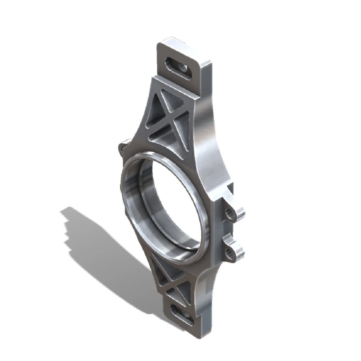
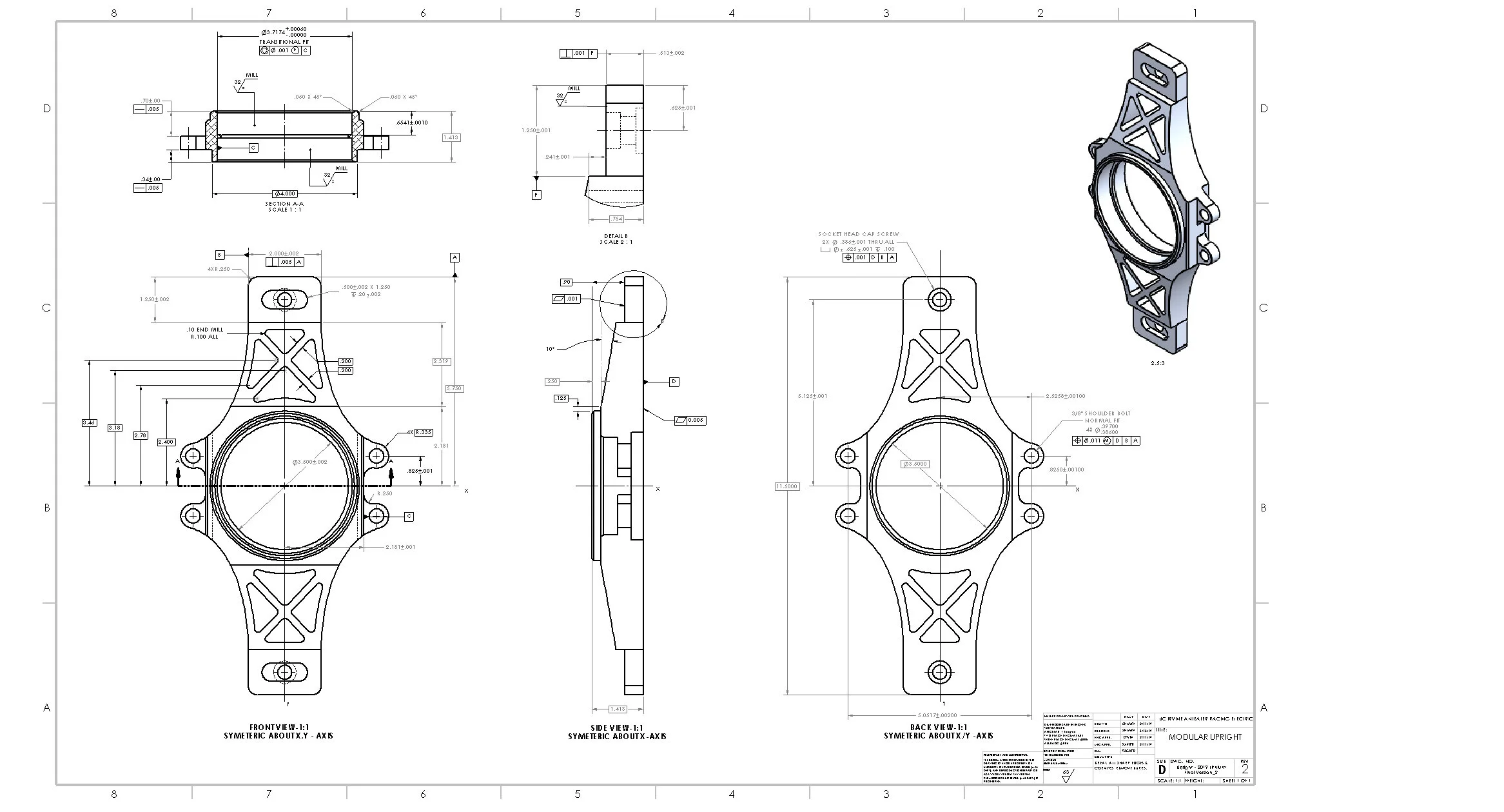
UC Irvine FSAE:
Anteater Racing Suspension System
Formula SAE Electric Race Team – Chief Mechanical Engineer & Suspension Lead
Organization: University FSAE Electric Division | Role held concurrently with undergraduate studies
Role: Chief Mechanical Engineer & Lead Suspension Engineer
Team & Project Overview:
Led the mechanical development of a single-seat, high-performance electric Formula-style race car for competition under the FSAE Electric rule set.
Oversaw mechanical systems integration across chassis, suspension, powertrain mounts, and aerodynamics under strict performance, safety, and weight constraints.
Leadership & Responsibilities:
Managed a team of 10+ sub-team leads and over 30 contributors, ensuring design quality, systems compatibility, and adherence to FSAE technical regulations.
Coordinated project timeline, design reviews, DVP&R documentation, and supplier communication for long-lead components and custom fabrication.
Design & Analysis:
Designed and validated 100+ custom mechanical components and 20+ full assemblies including:
Control arms, pushrod/rocker mechanisms, uprights, subframe mounts, and anti-roll bars
Machined aluminum suspension components and 4130 chromoly steel spaceframe structures
Conducted simulation-driven design using:
SolidWorks for CAD modeling and motion studies
ANSYS & SolidWorks Simulation for FEA, modal, and fatigue analysis
OptimumK and custom spreadsheets for suspension kinematics, anti-squat/dive tuning, and roll center mapping
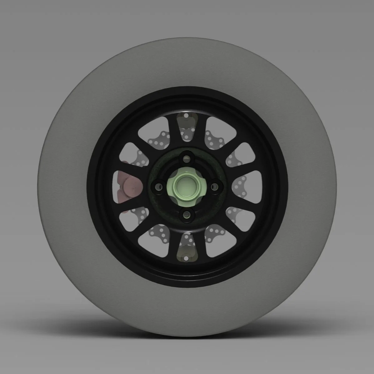
Suspension Engineering (Specialization):
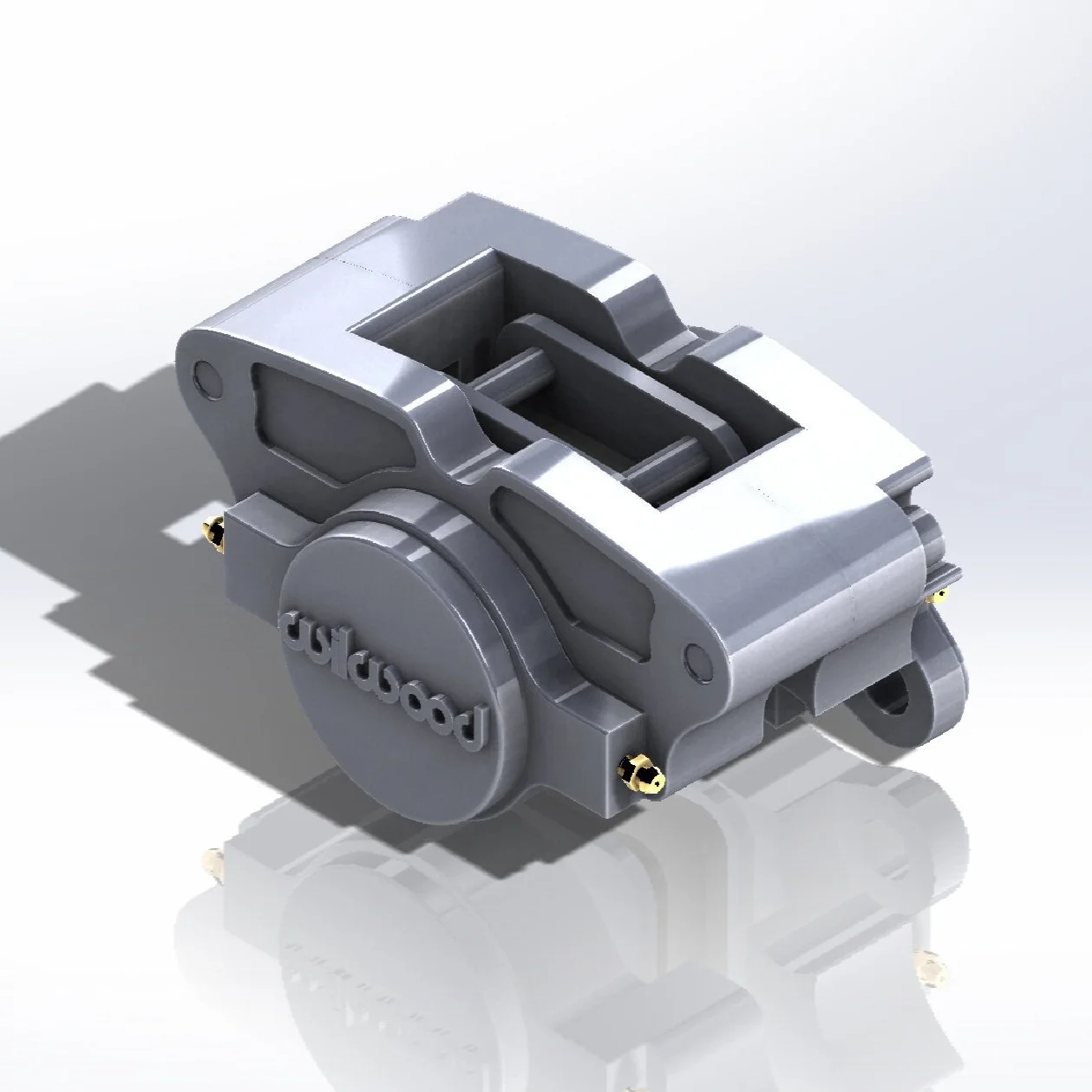
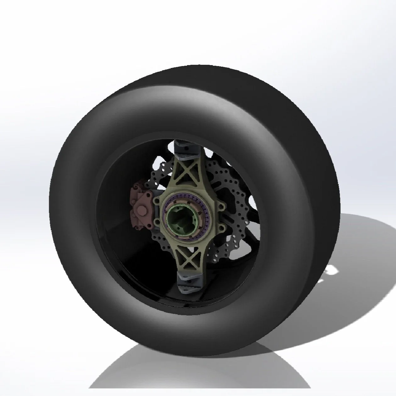
Led the design and testing of the double-wishbone suspension system with bell crank-actuated coilovers.
Tuned geometry for performance targets:
Ride height: 25 mm
Static camber: −2.5° front / −2.0° rear
Roll center height: ~30 mm above ground at static
Track width: ~1200 mm
Motion ratio: 0.9 (front), 0.85 (rear)
Validated loads via FEA (buckling and fatigue) and ensured safety factor >2.0 on high-stress components.
Manufacturing & Integration:
Directed fabrication and assembly of spaceframe chassis, suspension jigs, and carbon panels using:
CNC milling, TIG welding (4130 steel), waterjet cutting, and composite layups.
Developed DFM/DFA standards for component packaging and ease of service at competition.
Led the test-fit and shakedown phases, verifying suspension alignment, clearances, and dynamic behavior.
Outcome:
Delivered a fully integrated and track-tested electric race car meeting FSAE safety, performance, and design standards.
Represented the mechanical team during design judging at competition, presenting load paths, FEA results, and system justifications to FSAE industry judges.
Created in SolidWorks 2017


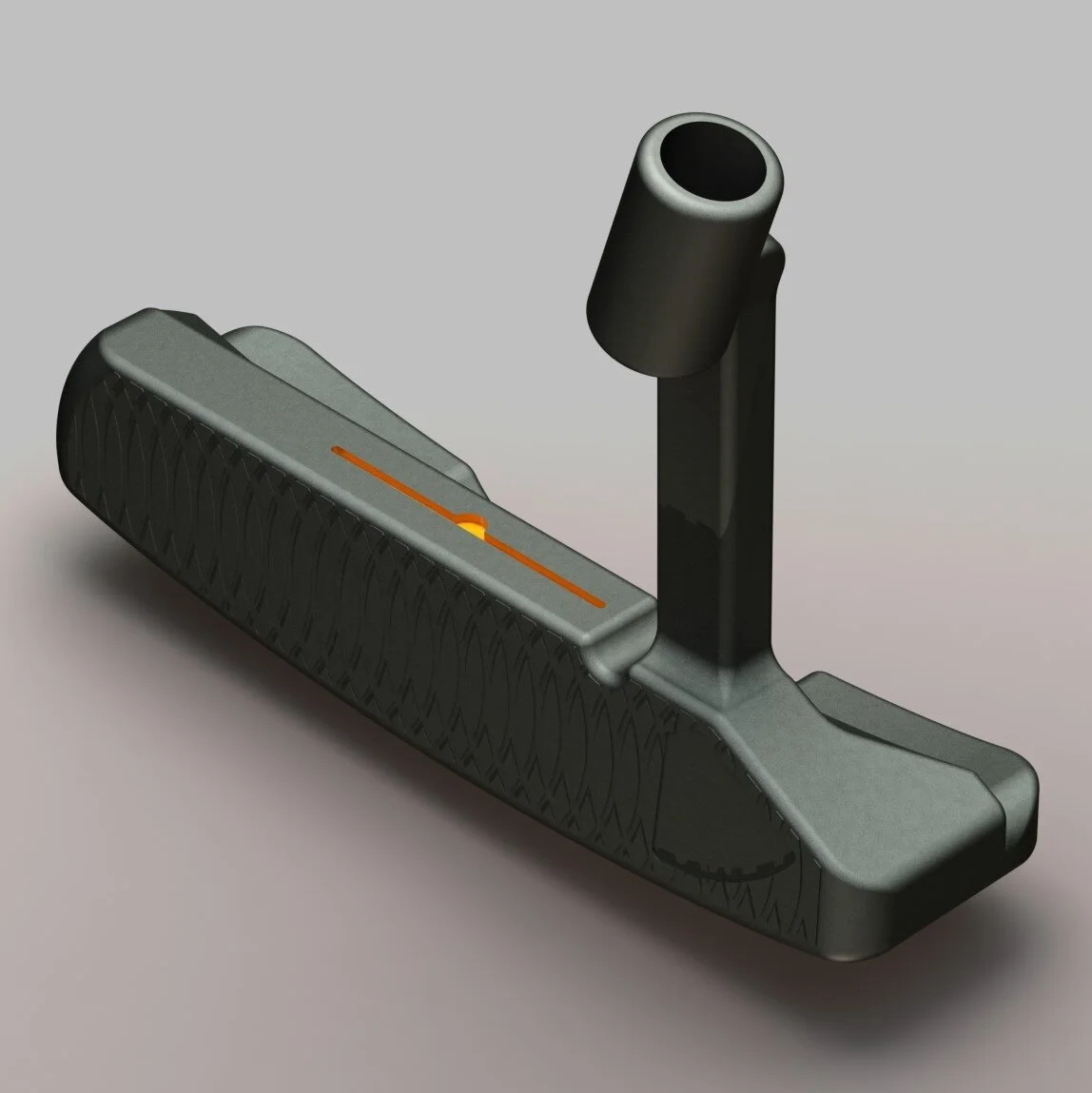
HONE Golf Co.
HONE Golf – Co-Founder, Chief Engineer, CAD & Manufacturing Lead
Role Summary: Co‑founded HONE Golf, overseeing end‑to‑end design, engineering, manufacturing procurement, logistics, and stakeholder coordination for blade‑style putters in both stainless and carbon steel.
Product Line:
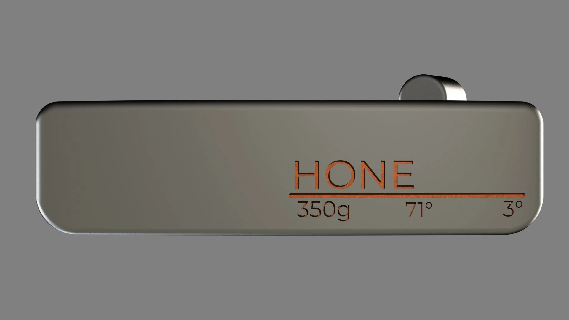
Developed two blade‑style putter designs—Apollo and Mercury—manufactured using two distinct materials:
303 stainless steel (Apollo): Offers a firmer feel, crisp audio feedback, and superior corrosion resistance.
1018 carbon steel (Mercury Carbon): Provides a softer touch and richer sound, but requires black‑oxide finish and maintenance to prevent rust.
Engineering & Design:
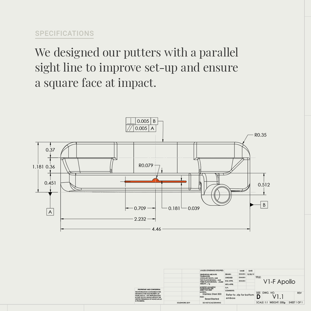
Designed all CAD models of putter heads and shafts using SolidWorks, including detailed sightlines, alignment features, and weight ports to ensure balance and stroke consistency.
Coordinated face milling specifications (deep face milling profiles) to optimize ball roll and tactile feel—leveraging insights that carbon steel gives softer feedback while milled 303 stainless yields more muted—but consistent performance.
Manufacturing Procurement & Logistics:
Managed relationships with CNC machining vendors focusing on precision milling of both stainless and carbon steel headstocks.
Oversaw production scheduling (1–2 week setup times), custom finish coordination (black oxide on carbon steel), and international shipping logistics from Corona Del Mar, CA.
Product Support & Marketing:
Collaborated with marketing to produce high-resolution product photography and description content, emphasizing contrast-aligned orange sightlines, finish options, and material differences.
Drafted maintenance recommendations for carbon steel models (e.g., towel drying, oil coating after exposure to moisture) to prolong product life and avoid rust.
Logistics & Order Fulfillment:
Coordinated order tracking, quality inspection, packaging, and customer shipments; ensured customization requests (e.g. grip length/length) were properly implemented before shipping.
Outcome & Differentiators:
Successfully launched two affordable, precision-milled blade putter models priced competitively (~$195 USD), blending traditional feel with modern manufacturing and aesthetic cues.
Emphasized alignment aids like high-contrast sightlines and center-dot placements to improve putter face alignment—a hallmark across both models.
Created in SoldWorks 2018/19


NERF Disruptor Modification – 3D Printing & Airflow Optimization
Course Project: Additive Manufacturing & Design Principles
Objective: Improve performance of a mechanical consumer product via CAD redesign and 3D printing
Project Scope:
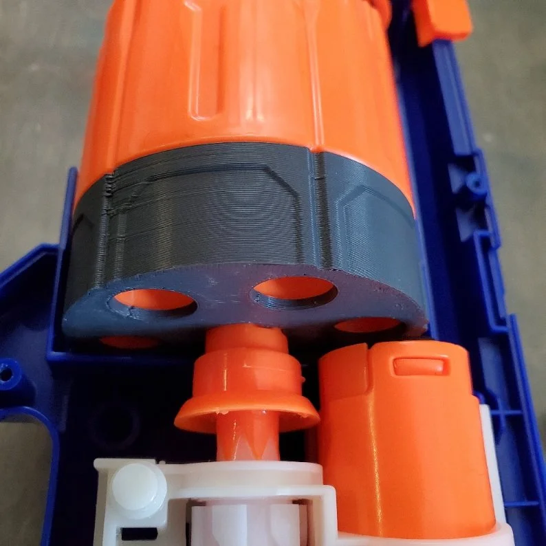
Selected a NERF N-Strike Elite Disruptor blaster as the base platform for performance enhancement via mechanical modification.
Focused on redesigning the barrel assembly and airflow path to increase dart velocity and range.
Design & Technical Approach:
Removed factory-installed air restrictors and dart guide posts, which were limiting airflow and increasing drag.
Reverse-engineered internal geometry using digital calipers and recreated the barrel and plunger tube interface in CAD (SolidWorks).
Designed and 3D printed a custom open-bore barrel insert using PLA for prototyping; included precision air seals for maximum pressure transfer.
Integrated design for drop-in replacement with no permanent alteration to the original housing.
Results:
Achieved a 200% increase in dart distance, from ~10 meters to ~30 meters, verified via repeated field tests at fixed angle and height.
Improved muzzle velocity through unrestricted airflow path and smoother barrel exit, confirmed via high-speed video and comparative analysis.
Demonstrated practical application of fluid dynamics, additive manufacturing, and consumer product reverse-engineering.
Outcome:
Delivered a functional prototype and full design package with STL files, dimensional drawings, and performance validation metrics.
Presented findings to class and received top evaluation for creativity, effectiveness, and design-for-manufacturing considerations.
Designed in SolidWorks 2020 - 3D Printed


